About this article
| Summary: | This articles shows a simple example of how to access the content of LCM Artifacts using ODI. You will learn the core concepts and techniques that would enable developers to combine the data of multiple artifacts and create advanced reports that aren’t available out of the box. The article focuses on two main parts: 1) Setting up ODI to access an XML file and view its information 2) Transforming LCM data to create a custom report It also includes tips and tricks how to resolve common issues with ODI and XML files. |
| Audience: | Hyperion/EPM administrators and consultants, ODI Developers |
LCM exports tell all – but can you read them?
If you’ve worked with Hyperion for a while, chances are you once have been going over all available standard reports, but couldn’t find one that gave you the answer you were looking for. Sometimes the information is only available in the XML files of an LCM export. Not sure if anyone would call “XML” a user-friendly format (see below), but there are some smart ways to format the information in LCM files (Celvin wrote a great article about this). If you have access to the relational databases of an on-premise environment, you can also write queries to create your own reports. Sometimes this isn’t quite as easy as hoped (or you might not even have access – if you are using the Oracle EPM Cloud), ODI could give you some additional options. This isn’t a quick fix, but might come in handy in certain situations.
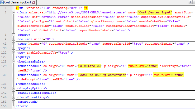
To keep this post as simple as possible, we will just use the XML file for a Planning Web Form and show the Business Rules that are triggered automatically when a user clicks the Save button.
First things first: what do we need
You need three things to follow the step-by-step guidelines in this article:
- XML File from an LCM export (if you don’t have one you can download the one I used). Make sure to remove/replace all spaces in the file name and path.
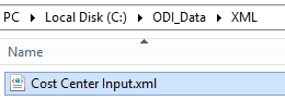
- Folder on the server/computer where ODI processes are running, e.g. C:\ODI_Data\XML: place the XML file in this folder
- Access to the Topology and Designer modules in ODI Studio
- ODI Topology is where you configure access to databases (and XML files) and define the Logical and Physical Architecture
- ODI Designer allows you to create Interfaces and Models (please note: in a Development environment you should be able to access the ODI Designer, but it might be required that you create a Development Work repository and connect it to an existing Master repository.)
Connecting ODI to your XML File
Configuring ODI to access an XML file takes a little effort and required some troubleshooting. I will walk you through all the steps you need to configure and show you the issues I faced along with instructions on how to work around them.
Topology for XML Technology
ODI’s Topology consists of 3 layers:
- Physical Architecture: we need to create a Data Server for the XML technology and set up a Physical Schema. This is where we define the path and name of the XML file as well as other parameters that are required to access the file. If you are familiar with ODI you will see that this is quite different from the setup you go through for a relational database for example.
- Logical Architecture: we need to create a Logical Schema (this is basically a name for the XML File, but it doesn’t have a reference to any specific file). All processes that you develop are based on the Logical schema, but will be translated to the Physical objects at design time
- Context: you need to link the Physical Schema to the Logical Schema. Depending on which Context you choose for executing your integration process, ODI will utilize different source files.
Step 1 – Open Topology in ODI: Log on to your ODI Development Work Repository, then go to View > ODI Topology Navigator
Step 2 – Create Data Server:
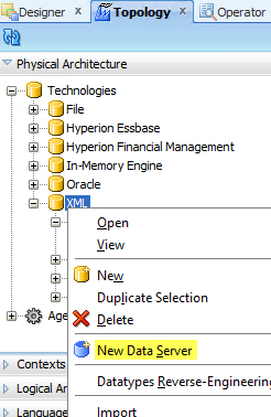
- Expand section Physical Architecture > Technologies, then scroll to the bottom and right-click on XML and choose New Data Server (note: if you don’t see XML listed under Technologies, click on the Topology icon in the top right corner of the Topology panel and uncheck Hide Unused Technologies)
- On the Definition tab:
- Enter the Name as XML_WEBFORM_DEV (doesn’t really matter, that’s just my personal preference as a naming convention which worked well for me: <Technology name, abbreviated>_<Server Name/Description>_<Environment Name>).
- No need to enter a Server name or User/Password
- One thing to be aware of is that you will need a separate XML Data Server for each XML file you are trying to integrate.
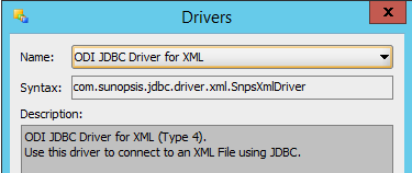
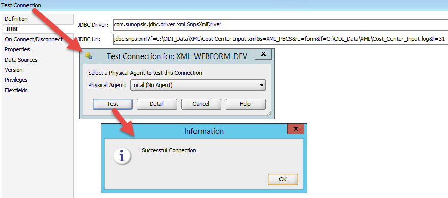
- On the JDBC tab
- Choose the JDBC Driver which uses the Java class com.sunopsis.jdbc.driver.xml.SnpsXmlDriver
- Enter the following information for the JDBC URL: jdbc:snps:xml?f=C:\ODI_Data\XML\Cost_Center_Input.xml&s=XML_PBCS&re=form&lf=C:\ODI_Data\XML\Cost_Center_Input.log&ll=31
- f:path and name of your XML file (make sure to remove spaces or replace them with underscores)
- s: name of Logical Schema
- re: root element
- lf: path and name of log file
- ll: log level (31 is the most granular value)
- For more information, see here
- Choose the JDBC Driver which uses the Java class com.sunopsis.jdbc.driver.xml.SnpsXmlDriver
Step 3 – Test Connection: click on the Test Connection button in the top left corner
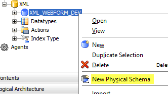
Step 4 – Create Physical and Logical Schema for Context DEV:
- Right-click on Data Server XML_WEBFORM_DEV and choose New Physical Schema
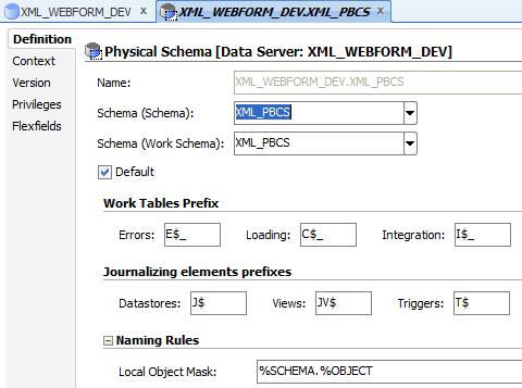
- On the Definition tab, choose XML_PBCS from the drop down (ODI pre-populates this field)
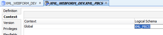
- Switch to the Context tab and enter XML_PBCS as the Logical Schema for Context Global
(note: the name of the Logical Schema needs to match value of parameter “s” which is defined in the JDBC URL of the XML Data Server)
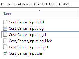
These are all the steps needed to define the Topology. While this looks pretty simple, there is actually a lot happening in the background: mostly obviously, ODI is generating the DTD file (Document Type Definition) for the XML file and it is locking files as you can see in the screenshot below. Looking at the log, there are many other steps as well.
A little advice on troubleshooting: the error messages are not always self-explanatory, but one simple tip to get around certain errors: shutdown ODI Studio and restart. This solves surprisingly many problems when you are first setting up the Topology and the Model. Sometimes you need to delete the lock files (.lck), but that isn’t possible if ODI Studio is running. The log file can also contain very helpful information.
Create an XML Model
We need to create a Model so we can access the content of the XML file. After defining the Model, fODI needs to reverse-engineer the Data Stores . Once we are able to do this successfully, we will be able to view and access the content of the XML file inside of ODI.
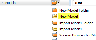
Step 1 – Create a new Model: Switch to the Designer tab and expand the Models section. Click on the icon in the top-right of the Model section and select New Model
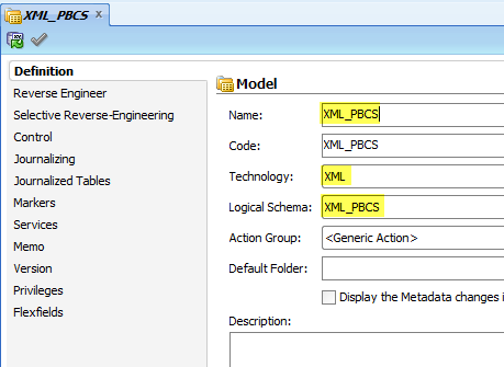
Step 2 – Define Model: Enter the information as in the screenshot below. Save the Model.
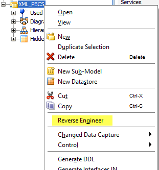
Step 3 – Reverse Engineer the Model:
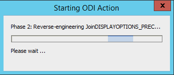
- Right-click on the Model and choose Reverse Engineer
- If everything is successful, this should take a few moments. You should see a pop-up like this:
Step 4 – View Data:
- Expand the Model and make sure all Data Stores are available
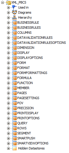
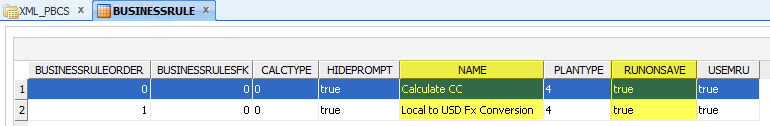
- View the content of Data Store BUSINESSRULE by choosing View Data from the context menu (right-click)
Ready to Build Reports?
Well, that’s all it takes to do the prep work to access information from an XML file. Now it’s time to put it all together and create our own LCM report. All we need is to create an Interface and transfer/transform the content of the XML file to a different medium (text file, database table, another XML file etc.)
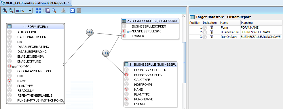
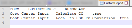
In our case, we are going to extract the Business Rule information highlighted in the screenshot above and combine it with information about the Web Form.
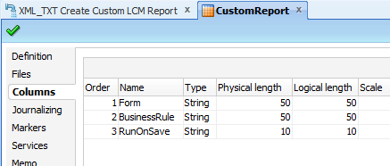
Step 1: Create a simple File Data Store with 3 columns that we can use as a Target:
- Form
- BusinessRule
- RunOnSave
Step 2 – Create an Interface: choose Data Stores FORM and BUSINESSRULE as the Sources and set File CustomReport as the Target.
- Joins will be created automatically based on the relationship between the different Data Stores of the XML file
- Mappings: see the screenshot
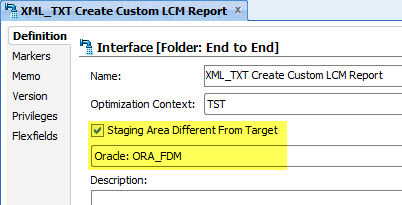
Step 3 – Choose the Staging Area to be different from the Target: since neither your source nor your target is a relational database, you need to define ODI’s Staging Area to be different than the Target (which is a text file). Any Logical Schema of a relational database can be used here.
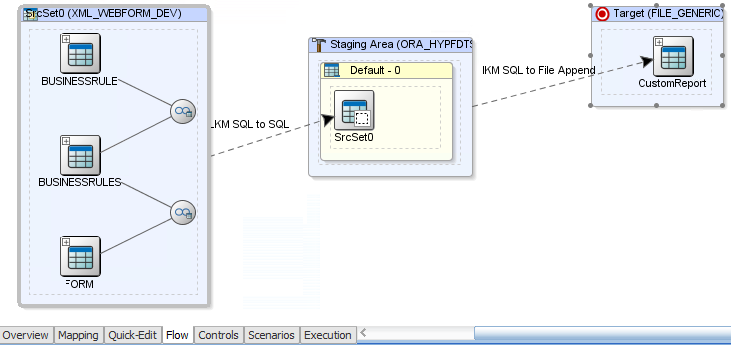
Step 4 – Define the Knowledge Modules on the Flow tab:
- LKM SQL to SQL
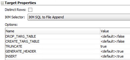
- IKM SQL to File Append
There is only one modification of the KM Options: set TRUNCATE to true
Step 5 – Report Output: after running the interface you can view the data in the generated file (the one here is tab delimited)
Wrapping up
Alright, that’s it. Hope this was detailed enough to understand what’s going on. Let us know if you are running into any issues or if you have any further questions.